By incorporating flexible design features in initial facility construction, biotechnology companies can move from pilot to production operations and market entry in a timely and cost-effective manner. This article describes a 30,000 ft2 facility designed to accommodate phase 1, 2, and 3 clinical trials.
The number of biologics approved for therapeutic applications and clinical trials is increasing. Early in 1992, the Pharmaceutical Manufacturers Association reported that 14 biopharmaceuticals were in development, with 58 companies involved in effort (1). By the end of 1992, FDA approved six more biologics – four therapeutics and two vaccines (2).
Of the many biologics in development and clinical trials, only a few will successfully reach commercialization. Most biologics are produced by either by cell culture (mammalian and insect) or microbial culture (bacterial and yeast). Facilities involved in producing biologics for clinical trial and final market entry must comply with a number of government regulations and conform to numerous “Guidelines” and “Points to Consider” documents issued by the Food and Drug Administration (FDA) (3-12).
Critical elements of regulations that apply to biopharmaceutical facilities have been previously reviewed (13-16). The volume of regulations, together with the complexities of the production technology involved, dictates that the construction and validation of biological production facilities is not a trivial financial or technical undertaking.
To Build or Rebuild?
Initially, for most biotechnology and pharmaceutical companies, a key decision is whether to build a new facility or to remodel an existing building. The next decision is whether to limit the operation of the proposed facility to pilot operation for phase 1 and 2 clinical trials or to build a facility capable of producing material for phase 3 clinical trials and market entry.
Frequently, it is more convenient and cost-effective to build a new facility than to renovate an existing building to function as a pilot facility (17). But in some circumstances this may not be the case. If the decision is to renovate an existing facility, attention should focus on separation of services (such as autoclave, water system, HVAC. and depyrogenation oven), raw material, product, and personnel flow from nearby research operations. If a facility’s scope includes eventual expansion for phase 3 clinical trials and early market production, the pilot facility should have the flexibility and elements to allow this. This adds to the initial cost of the facility but reduces unnecessary time loss that would occur if a new production facility were built after phase 2 clinical trials.
In this article we discuss design and operation of a 30,000i-ft2 research and pilot facility capable of producing biologics for phase 1,2, and 3 clinical trials and early market entry. This facility was built in an open space adjacent to existing research laboratories and office space. Its main function is to produce bulk, purified murine and chimeric motioclonal antibodies (Mabs) derived from cell culture and Mab fragments (Fab, Fv) derived from microbial culture. The antibody products produced in the facility are intended for radioimmunoconjugate MAb cancer therapy.
General Layout
Figure 1 illustrates the general layout of the facility. Administration, research areas, and quality control (QC) labs were already present in the facility. and the rest of the building was retrofitted to function as a pilot and production facility to produce biologics. The facility was sized to produce kilogram quantities of biologics derived from cell culture and microbial sources for all phases of clinical trials and early market entry.
A linear, unidirectional flow of operations is preferable. But in this case, structural constraints necessitated a circular unidirectional flow for the cell culture facility to prevent the mixup of clean and used equipment and glassware. The microbial facility is physically separated from the cell culture facility with its own dedicated single-pass heat ventilation and air-conditioning (HVAC) system. Furthermore, entry to the research area is separate from the production area (RE and PE, in Figure l).
The research area consists of three 600-ft2 molecular biology laboratories where chimeric, humanized, bacterial- and yeast-derived antibody and antibody fragment-secreting clones are engineered. The cell culture research and process development laboratory is located in this area, Cell culture process development uses five 2-L bioreactors and one 40-L bioreactor. Cell culture is generally performed under antibiotic-free conditions.
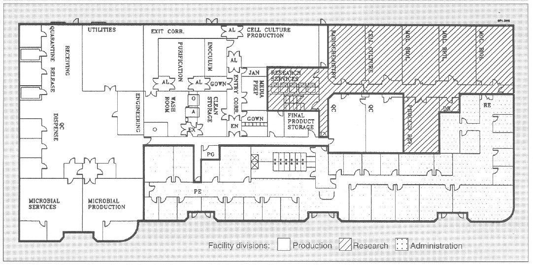
Figure 1. General facility layout for a flexible, biopharmaceutical pilot facility with a 30,000-ft2 area. AL = airlock; EN = entry airlock; EX = exit airlock;O = GMP depyrogenation oven; A = GMP autoclave; Utilities = UHQ water, pure steam, plant steam; Entry Corr = entry corridor to cell culture facility; Exit Corr = exit corridor from cell culture facility; QC = quality control; Mol Biol = molecular biology laboratory; RE = research laboratory entry/exit; PE = production facility entry/exit; PG = pregowning room; Jan = janitorial supply room; DR = dark room; PG = pregown room.
To minimize contamination, cell culture research and cell culture process development laboratories are equipped with Cleanroom washable ceiling tiles and ceiling HEPA-filtered air that reduces particulate (0.2- and 0.5-μm) count of 100,000-300,000 by 10- to 30-fold. The research laboratories are serviced by a single-pass HVAC system and have a slight negative pressure with respect to the corridor. This reduces cross contamination between different laboratories. The research area has its own dedicated autoclave, reverse-osmosis and deionized (RO/DI) water system, depyrogenation oven, dishwashers. and dryers (Figure 1).
Cell and Microbial Production
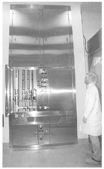
Figure 2. View of a general purpose service panel providing air. nitrogen, oxygen, and carbon dioxide services to bioreactors and process equipment.
The cell culture facility comprises a gown room, a wash room. a clean storage area, a medium preparation area, an inoculum preparation area. a cell culture production area. an entry and exit corridor, and associated airlocks (Figure I). The cell culture production area is a 1250-ft2 with a 14- foot hard ceiling to accommodate a variety of bioreactors and process equipment, The cell culture production area is isolated from the rest of the facility by two airlocks that are pressurized in both directions (EX and EX, Figure 1). To enter cell culture facility production, personnel must pregown (PG, Figure 1), and after passing through the cell culture facility airlock (EN) they must gown in a EPA-filtered gowning room (supplied with terminally HEPA-filtered air at 250 changes per hour). In this gowning room, the large volume of laminar airflow substantially reduces introduction of particulate matter by personnel. Exit from the cell culture facility is through an exit-only corridor, through the wash area, through the exit airlock, and out of the facility(EX).
Utility panels. Three utility panels (Figure 2) can service three bioreactor skids or other process equipment in the cell culture production area. Each utility panel was designed to provide flexibility to operate any type of bioreactor: hollow-fiber, stirred-tank, airlift, and other process equipment. Each utility panel is equipped with the following services: pure steam, gasses (air, oxygen, nitrogen, and carbon dioxide). A vent for bioreactor exhaust gases. capped drain, chilled water, potable water, ultra high quality (UHQ) water, and 110- and 208-V electricity. Because of continuous improvements in cell culture methodology and the need to grow either suspension or anchorage-dependent cells. flexibility is essential in the design of a cell culture pilot and production facility. Inoculum seed cultures are prepared in the inoculum reparation room. and purification and simple chemical modification of proteins are performed in the purification area (Figure 1). Cell culture production and purification are isolated by their respective airlocks. Purification has a secondary gowning room. Media are prepared in the medium preparation room in 15- 500-L medium preparation vessels. Process equipment is washed, steam sterilized, autoclaved, and depyrogenated in the wash room and stored in the clean storage room (Figure 1).
Bioreactor. A unique bioreactor (Figure 3) was designed to service the flexible requirements of large-scale cell culture of mammalian and insect cells. The bioreactor consists of one 100-L vessel and three 400-L working volume vessels. This system is capable of 100- and 400-L batch culture in airlift. stirred. or airlift-stirred combination mode. This is possible because of the flexible design of the bioreactor, in which draft tubes, baffles. or impellers can be added or removed from the bioreactor vessel. Semicontinuous culture can produce 50-200 L of tissue culture harvest per day. The 100- and 400-L vessel can also be perfused with fresh media while cells are retained within the bioreactor during perfusion culture. This results in 150-600 L of high cell density, 5-15 million cells/mL of cell culture harvest. Microcarrier culture in 100- and 400-L/batch or 150-600 L/day perfusion mode can also be performed by the bioreactor, The cell culture production area can accommodate three such bioreactors.
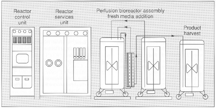
Figure 3. An “all in one” bioreactor with three 500-L tanks and one 100-L. tank (above and below). The diagram (above) depicts a perfusion assembly in which cells growing in a 400-L vessel are recirculated through a hollow-fiber back to the bioreactor while the product is harvested in the product harvest tank. Fresh media is added to the bioreactor by a third tank. Each vessel is equipped with a removable draft tube and an impeller with an adjustable height on the agitator shaft.
Both in-process and final bulk products are stored in final product storage (Figure 1) where they are released for further processing after appropriate quality control (QC) testing.
The microbial production area (Figure 1) is equipped with separate dishwashing and autoclave services. This area can accommodate a 100- and 1,000-L working volume bioreactor operating in batch mode.
Purification area. A number of large-scale processes are available to purify secreted or nonsecreted biologics from microbial and cell sources (18), Bulk, cell-free, concentrated harvest from cell culture and microbial production (microfiltered and ultrafiltered) is purified in the purification area (Figure 1). Low-, medium-, and high- pressure liquid chromatography can be used to produce kilogram quantities of bulk biologic in the purification area. Temperature control is provided by either HEPA-filtered refrigerators or temperature controlled jacketed buffer tanks and columns. Bulk biologic produced from cell culture and microbial sources is stored in final product storage and. after QC release, is vialed in a separate facility.
One product at a time is processed in either the cell culture or microbial production area and then processed in the purification area to prevent mixing of the product with raw or in-process material. The facility is completely cleaned after each product campaign. Facility access areas are cleaned daily, and the entire facility is cleaned weekly from ceiling to floor. Cleaning detergents are rotated biweekly.
Cell culture and purification waste is chemically decontaminated, and pH is neutralized using a 500-L working volume chemical kill system. Microbial waste is heat inactivated before disposal. Production and research areas are serviced by a separate drain system.
Utilities and Services
Utilities for production operations are located in the utility area (Figure 1). A 2,000-lb/hour plant steam boiler provides raw steam with no chemical additives for pure steam generation from UHQ water (located adjacent to the plant steam boiler) and also provides humidity for HVAC and waste autoclave located in the washroom. A 1,000-lb/hour pure steam generator provides pure steam for bioreactor sterilization and GMP autoclave chamber and jacket.
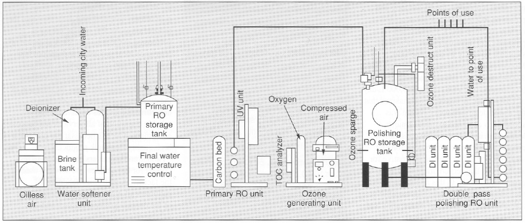
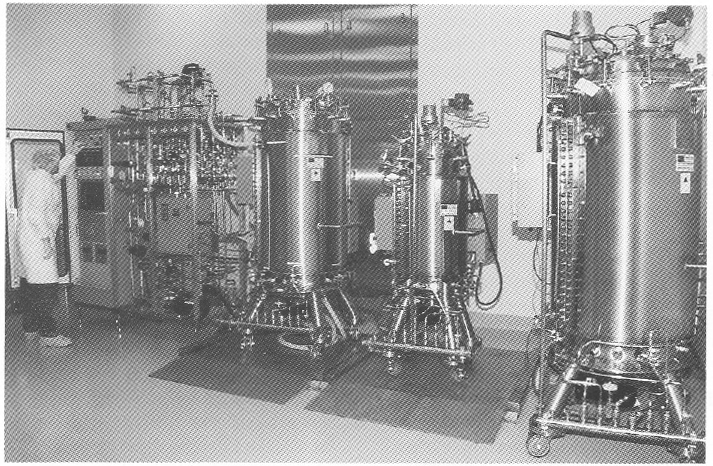
Figure 4. View and diagram (above and below) of a 13-gpm UHO water system providing 18-megohm metal-tree water with, 10 ppb of total metal content. This meets and exceeds WFI specification for the production of protein-chelator complexes tor radioimmunoconjugate application.
Depyrogenation. Pyrogens from bacterial residues can be a major contaminant of process equipment. A number of methods are available to remove pyrogens (19). A double-door depyrogenation oven (O, Figure 1) with a 30-ft3 chamber depyrogenates heat-resistant glass and stainless steel components at 250 °C. A double door GMP autoclave (A, Figure 1) with a 60-ft3 chamber provides autoclaving services. The microbial facility is equipped with a separate 15-ft3 autoclave and dishwashing services.
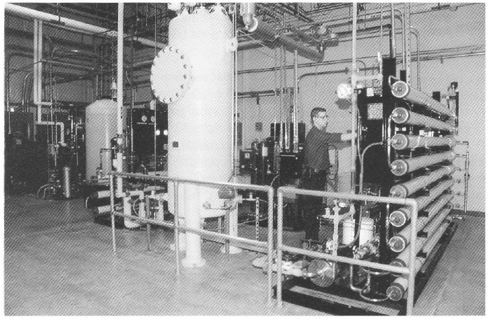
Special water requirements. The product being produced in this facility is an antibody conjugated to an organic chelator that binds a radioisotope (90 Yttrium). The final product is an unbound antibody conjugate for which chelation to the radioisotope 90Y is performed at the hospital. For this class of products, very low concentrations (less than 10 ppb or μg/L) of total metal are necessary for water used for final product purification and processing. Metal contaminants from traditional stainless steel, multiple-effect, and vapor compression water for injection (WFI) systems will bind the chelate and adulterate the final product (20). Traditional WFI distribution systems where water is recirculated in an 80 °C stainless steel hot loop cannot reliably produce water with the required low total-metal content. To address the special water requirements. a unique 13-gpm, continuous-flow. three-pass reverse-osmosis (RO) water system (Figure 4) was designed to produce pharmaceutical-grade UHQ water suitable for final product processing.
To guarantee high water quality, a storage tank is located in front of the final double-pass polishing RO membranes. Water is directly circulated to points of use from the polishing RO membranes at a rate of 13 gal/min (approximately 75,000 L/day). The quality of water used in this process is similar to type E-l water produced for use in the electronics industry and is of much higher purity in terms of metal, organic, endotoxin. and microbial contaminants when compared with water from traditional pharmaceutical- grade stills.
Water recirculates in a piping loop constructed of polyvinilidine difluoride (PVDF). To maintain low endotoxin and microbial bioburden, the PVDF loop and polishing RO storage tank are ozoneted nightly for three hours. Primary and polishing RO membranes are chemically sanitized biweekly by peracetic acid. Moreover, to prevent microbial growth. The 1,000-L polishing RO storage tank (constructed of PVDF) discards 8,000 L/day of UHQ water. It should be emphasized that the above-described water system was specifically designed to meet at unique application in biotechnology purification process development and production and should not be considered an alternative for applications that require traditional WFI, generated by stills. In this application, traditional WFI, with its higher metallic contaminants, would be an adulterating and contaminating agent for the final immunoconjugate products.
HVAC units. Special considerations determine the design of HVAC systems for biologics pilot production facilities (21, 22). Separation of HVAC units is necessary for critical processes to prevent cross-contamination of air. In the facility discussed here. the cell culture inoculum area, cell culture production urea, and associated airlocks are serviced by one HVAC unit. The purification area and its associated airlocks are serviced by another HVAC unit. Air entry into each room is terminally HEPA-filtered at the ceiling with 25 air changes in the cell culture inoculum and cell culture production areas and 50 air changes in the purification area. As currently configured, air is recirculated at a rate of 80% in the above areas and meets the requirements of biosafety level 1 (BL-1); however, the HVAC system can be modified to generate single-pass air for biohazard process applications and applications higher than BL-1.
| VALIDATION PARAMETERS |
| The following are validation parameters for key utilities and services |
| GMP autoclaves. Overkill cycle, 60 minutes at 121°C at 15 psi. No survival of Bacillus stearothermophilus spores at a population of 106 |
| Pure steam generator. Condensed pure steam meets USP WFI specifications. Endotoxin <0.125 EU/ml, and microbial content <1 Cfu/100 mL. |
| Depyrogenation oven. 60 min. cycle at 250°C. <100 0.5 μm particles/ per ft3 of 0.5 μm size. Minimum of 3 log endotoxin reduction. No survival of Bacillus subtilus at a population of 106. |
| Ultra high quality water. <10 ppb of metals (such as Ni, Cu, and CO), <10 PPB of organics; <0.03 EU/mL of endotoxin; and <1Cfu/100mL. Resistivity 15-18 megohm. Meets and exceeds USP specifications for water for injection (WFI). |
| HVAC and environmental baseline. Controlled areas except wash and microbial production (10,000 particles/ft3/min) and wash room and microbial production (100,000 particles/ft3/min). < 25 viable organisms/10 ft3 of air; temperature 23±3°C; and humidity 40-60%. |
A dynamic particulate count of < 10,000 is maintained in both the production and purification areas. Counts of < 1,000 are typical during operation. Airlocks adjacent to the facility are all at positive pressure (with respect to both the facility and its exterior) to prevent particulates from either entering or exiting the facility.
A third HVAC unit services the media preparation and clean storage areas and the clean corridor where air passes once from the clean areas and exits into the exit corridor and the wash room. The particulate count in the clean storage and media preparation areas and the entry corridor is maintained at a particle count of < 10,000 during active periods. The particulate counts in both the exit corridor and the wash room are maintained at < 100,000 during active periods. Because large-scale production of biohazardous microorganisms requires both single-pass air and at backup HVAC, a fourth HVAC backup unit can be used if there is a need to comply with HVAC requirements of large-scale BL-2 (23). Currently, the facility operates at BL-1 level. All processes are performed in closed vessels (production, microfiltration, ultrafiltration, and purification), and large process vessels are isolated from the environment by 0.2-μm filters.
The microbial production area is serviced by one centrally HEPA-filtered, single-pass HVAC that provides a production area with a particle count of <100,000.
Validation. Raw materials are delivered to the receiving area (Figure 1] and then quarantined, released, and dispensed into the production areas. QC release testing is performed in QC laboratories. Validation of pharmaceutical processes and utilities has been previously discussed (24). A comprehensive validation and preventive maintenance program under the direction of the quality assurance and production departments provides continuous and reliable operation of all services and process equipment, which is necessary to produce a high quality final bulk product. The “Validation PARAMETERS” box summarizes criteria for key utilities and services used in the facility. A metrology laboratory calibrates all processing equipment as part of the overall quality assurance and validation program.
Because all biologics are thermolabile, terminal sterilization cannot be used to produce sterile bulk product, Instead, aseptic filtration is used before vialing. Stability of the cell lines (measured by specific activity and specific productivity of cell line), in-process product, and final bulk stage is assessed mainly by physiochemical protein analytical techniques (25). Final product is vialed under liquid or lyophilized conditions in at separate dedicated facility.
Maximizing Flexibility
The flexible pilot-production facility described here is capable of producing gram to kilogram quantities of biologics for research. All phases of clinical trials. And early market entry. Key features of the present facility are its flexibility in handling a variety of cell culture processes and bioreactors; a novel bioreactor system that can operate in a number of modes to meet the diverse needs of cell culture production processes; and a unique UHQ water system with 10-ppb metal concentration.
These design features will assist new biotechnology operations in designing flexible operations lo meet their internal research. clinical, and market-entry requirements, all while minimizing cost and maximizing flexibility. speed, and efficiency.
References
(1) In Development Biotechnology Medicines (Pharmacetical Manufacturers Association, Washington, D.C., 1992)
(2) T.L.Copmann, “FDA Approves 6 Biologic Therapeutics and Vaccines, “New Drug Approvals in 1992 (Pharmaceutical Manufacturers Association, Washington, D.C., 1993), pp. 5-6
(3) Code of Federal Regulations, Title 21, Parts 600-680 (U.S. Government Printing Office, Washington, D. C. 1992).
(4) Code of Federal Regulations, Title 21, Parts 200-211 (U.S. Government Printing Office, Washington, D.C. 1992).
(5) “Points to Consider in the Characterization of Cell lines Used to Produce Biologicals” (Food and Drug Administration, Bethesda, MD, 1987).
(6) “Points to Consider in the Manufacture and Testing of Monoclonal Antibody Products for Human Use” (Food and Drug Administration, Bethesda, MD, 1987).
(7) “Points to Consider in the Manufacture and Testing of New Drugs and Biologicals Produced by Recombinant DNA Technology” (Food and Drug Administration, Bethesda, MD, 1985).
(8) U.S. Federal Standard 209D, Clean Room and Work Station Requirements.
(9) Guideline on Sterile Drug Pruducts Produced by Aseptic Processing (Food and Drug Administration, Bethesda, MD, 1987).
(10) Guideline on General Principles of Process Validation (Food and Drug Administration, Bethesda, MD, 1987).
(11) Proposed GMP for Large Volume Parenterals, 21 CFR, section 212, 1976.
(12) US. Dept. of Health and Human Services, Biosafety in Microbiological and Biomedical Laboratories, (U.S. Government Printing Office, Washington, D.C., 1984).
(13) D. Hill and M. Beatrice , “Biotechnology Facility Requirements, Part 1, Facility and Systems Design,” BioPharm 2 (9), 20-26 (1989).
(14) D. Hill and M. Beatrice , “Biotechnology Facility Requirements, Part 2, Operating Procedures and Validation,” BioPharm 2 (10), 28-32 (1989).
(15) P.L. Simmons, The Impact of GMPs on the Manufacture of Bulk Pharmaceticals Chemicals/Biologics (ICT2, Miami, FL., 1988).
(16) P.L. Simmons, The Design, Construction and Commissioning of a New Facility in Accordance with GMP Regulations (ICT2, Miami, FL., 1988).
(17) D. Robin and R. Del Ciello, “To Renovate or Build New; Guidelines for Evaluation Construction Alternatives,” BioPharm 1 (1), 34-38 (1988).
(18) R.J. Giorgio, “Facilities for Large-Scale Protein Purification and Isolation,” BioPharm 1 (5), 38-46 (1988).
(19) M. Weary and F. Pearson III, “A Manufacturer’s Guide to Depyrogenation,” BioPharm 1 (4), 22-29 (1988).
(20) E.E. Bjurstrom and D. Coleman, “Water Systems for Biotechnology Facilities,” BioPharm 1 (0), 50-55 (1987).
(21) S.L. Kelter, “An HVAC Primer for Biopharmaceutical Facilities,” BioPharm 1 (5), 30-37 (1988).
(22) J.Y. Lee, “Environmental Requirements for Clean Rooms,” BioPharm 2 (2), 42-45 (1989).
(23) R.Z. Maigetter, F.J. Bailey and B. Miller, “Safe Handling of Microorganisms in Small- and Large-Scale BL-3 Fermentation Facilities,” BioPharm 3 (2), 22-29 (1990).
(24) F.J. Carleton and J.P. Agalloco, Validation of Aseptic Pharmaceutical Processes (Marcel Dekker Inc., New York, 1986).
(25) “Assessment of Genetic Stability for Biotechnology Products,” Pharmaceutical Manufacturers Association 4 (2), 22-27 (1991).